The Steam Room
A Walking Tour
by Steve Andrews
The Steam Room has a varied collection of stationary steam engines that represent several different valves and governors. We have a piston valve engine, several slide or “D” valves and three Corliss valved engines, two of which are non-releasing and one that does release. There are some engines that have flyball type governors, and three that have governors designed into the flywheels.
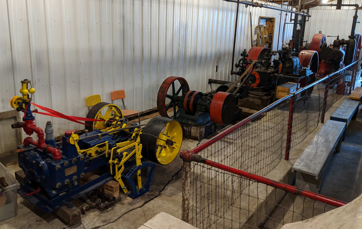
The first engine on your right as you enter the steam room is an Ideal Engine, built by A. L. Ide and sons, Springfield, Illinois. It is piston valved and sports a steam separator; the vertical black tank near the cylinder. The flywheel governor is very noticeable on this engine, and shows the principle of operation. The Ideal has an enclosed crankshaft and part of the lubrication is the same splash type used in internal combustion noisemakers.
The next engine is of an undetermined make and is on the injured list with a maladjusted crankshaft. It is a project on the list of things to do, but it does have an interesting physical property. Since its injury, it has attracted buckets of oil, hoses, assorted articles fashioned of metal that display an interesting patina of rust, and one huge clevis. I’m concerned that this brood is breeding and multiplying.
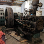
Mankato is the birthplace of the next horizontal. This is the first engine I started with Charles Loken instructing. It is out of a creamery, I don’t know which one, but provided belt power to a line shaft. If has a flyball governor and centrifical force moves the balls outward. The shaft to which they are attached is fixed to a balanced valve to regulate the steam allowed into the steam chest, thus controlling the speed. The valve is the “D” type.
Next are two verticals. They sat unattended for several years until 1992 when they were reattached to the steam line. The larger is enclosed, but the smaller is a cute unit that reminds me of the provider of power on the African Queen.
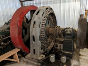
Park Region Dairy was the previous home of the red non-releasing Corliss in the corner. It was also made by E. A. Ide & Sons, thus we have the Ideal Corliss. This unit like the one up front is designed to generate electricity, so the flywheel governor is attached to the rods evident on the engine. The top set operates the steam admission, while the bottom ones control the exhaust. This engine, designed to run at 200 rpm is run here at a slower speed, making it a drain on the head of steam we have, so if is only run on a sporadic basis.
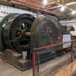
Browerville creamery provided the Chuse Corliss, the green one. It is another steam consumer, so we have it on the same diet as the Ideal. The governor operates on the same idea as the other, but has a different way of regulating the steam. I should add, both non-releasing Corlisses have steam separators above their steam chests.
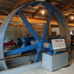
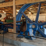
Now we come to the queen of the steam room, the Allis-Corliss. This beauty powered at least one line shaft at the REO truck plant in Detroit. Built in 1906 it runs well and the rhythmic clicking of the releasing valves provides the pacifying sound that hypnotizes those watching and listening. The engine itself is girder framed, and turns a flywheel of about 15 feet. The flyball governor controls the reach rods that, in turn, trio the cutoff valves for steam admission. Those things on the floor that go “chung” are dash pots. In normal operation, these would be creating a near perfect vacuum to pull their pistons back to ensure an immediate cutoff of steam admission. The piston is 20 inches in diameter with a 42 inch stroke. This engine runs all day, sipping steam, and provides all with a sense of awe. Another item of interest on the flywheel, if you watch the spokes you can see the wood grain of the original casting pattern.
The crew of the steam room are always at your disposal so don’t be afraid to ask. You may have to let them break away to feed the boiler, it eats a lot of wood and water, but they’re ready to explain or find the answer.

